MIL-DTL-24643C
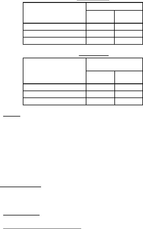
TABLE II. Armor braid angle.
Braid angle
Diameter over jacket
Min.
Max.
(inches)
(degrees)
(degrees)
0.100 - 0.600
30
60
0.601 - 1.000
35
60
1.001 - 1.500
40
70
TABLE III. Wires per carrier.
Max. number of
ends/carrier
Diameter under braid
(inches)
One over
Two over
One under
Two under
0.100 - 0.400
8
5
0.401 - 0.800
12
10
0.801 - 1.500
16
10
3.4.5.1 Coverage. The coverage shall be as determined by the following formula:
Percent coverage = 100 (2F-F2)
Where:
F
=
NPd/Sin (a)
Tan (a)
=
2 × 3.14159 (D+2d)P/C
a
=
acute angle of braid with axis of cable
d
=
diameter (inch) of individual braid wires
D
=
diameter (inch) of cable under braid
N
=
number of wires per carrier
C
=
number of carriers
P
=
picks per inch of cable length
3.4.6 Dimensional tolerances. Where minimum or maximum dimensions, or both are specified, no minus or
plus tolerances, respectively, shall be permitted. Where no minimum overall cable diameter is specified, the
minimum permissible diameter shall be not less the 92½ percent of the specified maximum overall cable diameter.
NOTE: Caution should be exercised when designing armored cables since the use of 28 AWG aluminum armor
results in an actual increase in overall diameter of as much as 0.060 inch.
3.4.6.1 Nominal dimensions. Where a dimension is specified as nominal, it shall be for reference purposes
only and shall not be construed as a requirement.
3.4.6.2 Extruded and taped insulation wall thickness. For conductor insulation wall thickness specified as
minimum average, the minimum thickness, measured at any cross-section, shall be not less than 90 percent of the
specified minimum average.
11
For Parts Inquires call Parts Hangar, Inc (727) 493-0744
© Copyright 2015 Integrated Publishing, Inc.
A Service Disabled Veteran Owned Small Business