MIL-DTL-24643C
4.8.22.3 Procedure. The specimen shall be secured in a vertical position, the terminal fitting (including the
plug) shall be fitted over its upper end, and the hardening sealant shall be poured through the appropriate terminal
fitting aperture to bond the fitting to the specimen. These shall be done such that the specimen is approximately
centered within the terminal fitting, such that not more than a 6-inch length of specimen jacket is exposed to the
sealant, such that the end face of the specimen is located a distance of not more than 1 inch above the sealant surface
and itself contains no sealant, and such that the aperture through which the sealant was introduced is itself made
pressure-tight. The sealant shall be allowed to harden, following which the terminal fitting plug shall be removed or
cut away to the extent that it exerts no radial compression on the specimen. The specimen shall then be positioned
such that it is straight, and such that no portion of the specimen is at a greater elevation than the specimen end within
the terminal fitting. The fitting shall then be connected to the source of pressurized water, and excess air within the
fitting shall be bled off until it can be certain that the entire enclosed specimen end face is exposed to the pressurized
water for the remainder of the test. The source of pressurized water shall be slowly raised to 27.5±0.5 lb/in2 over a
period of 3±0.5 minutes and remain connected to the fitting for a continuous period of 6+¼, -0 hours. During this
test period, water (if any) leaking from the specimen end opposite the terminal fitting shall be collected into an
initially dry container. Following the test period, the volume of this collected water shall be measured.
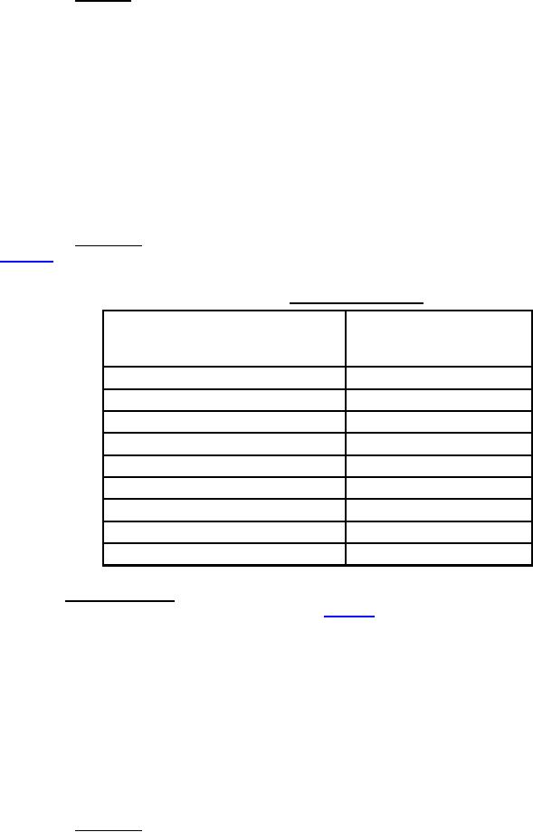
4.8.22.4 Observation. Specimen failure shall be construed if the collected water volume exceeds that shown in
table XIII.
TABLE XIII. Limits for water leakage.
Sum of specified cross-sections
Collected water volume
of all specimen conductors
(cubic inches, max.)
(see 3.1) (circular mils)
Less than 9,001
4
9,001 to 15,000
5
15,001 to 25,000
6
25,001 to 50,000
8
50,001 to 100,000
9
100,001 to 200,000
10
200,001 to 500,000
11
500,001 to 800,000
12
800,001 or greater
13
4.8.23 Acid gas generation. The method given below is to determine the total emission of any strong soluble
acids (pH less than 3). The required apparatus is shown on figure 14. A weighed sample of the jacket, fillers, and
insulation materials (for component wire, use insulation removed from a 22 AWG wire), normally ¼ to ½ gram,
shall be placed in a silica boat which is put into the center of a silica tube, length 50/60 centimeters and internal
diameter 20/22 millimeters. The material shall be tested individually. The silica tube shall be placed in the tube
furnace. An air supply, derived from a blower or compressed air cylinder, at the rate of 1 liter per minute ±5 percent
shall be passed through the silica tube and then through four absorber flasks each containing 30 milliliters of
deionized water. The furnace heating shall be commenced and the temperature of the tube and sample shall be
raised to 800±10 °C over a period of approximately 40 minutes and then held at temperature for a further 20
minutes. During the heating period, any acid gases produced will be carried over into the absorber flasks. On
completion of the heating cycle, the acid content of the fluids in the absorber flasks shall be titrated against 0.1 N
sodium hydroxide solution using congo red as an indicator. The total titrate indicates the total soluble acids. 1.0 mL
of 0.1 N sodium hydroxide solution is equivalent to 3.65 mg of acid expressed as "acid equivalent relative to
hydrochloric acid."
4.8.23.1 Observation. Specimen failure shall be construed if the acid equivalent exceeds the percentage, by
weight of the sample, specified (see 3.1).
47
For Parts Inquires call Parts Hangar, Inc (727) 493-0744
© Copyright 2015 Integrated Publishing, Inc.
A Service Disabled Veteran Owned Small Business