MIL-DTL-24640C
CONDUCTOR PAIR PLUS SURROUNDING
SHIELD WITHIN SPECIMEN
PULSE
GENERATOR
INPUT
OUTPUT
PULSE
PULSE
TRANSFORMER
TRANSFORMER
OSCILLOSCOPE
SIGNAL
SIGNAL
CHANNEL
CHANNEL
NO. 1
NO. 2
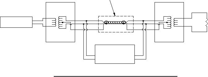
FIGURE 13. Block diagram of electrical connections for the pulse response test.
61
For Parts Inquires call Parts Hangar, Inc (727) 493-0744
© Copyright 2015 Integrated Publishing, Inc.
A Service Disabled Veteran Owned Small Business